

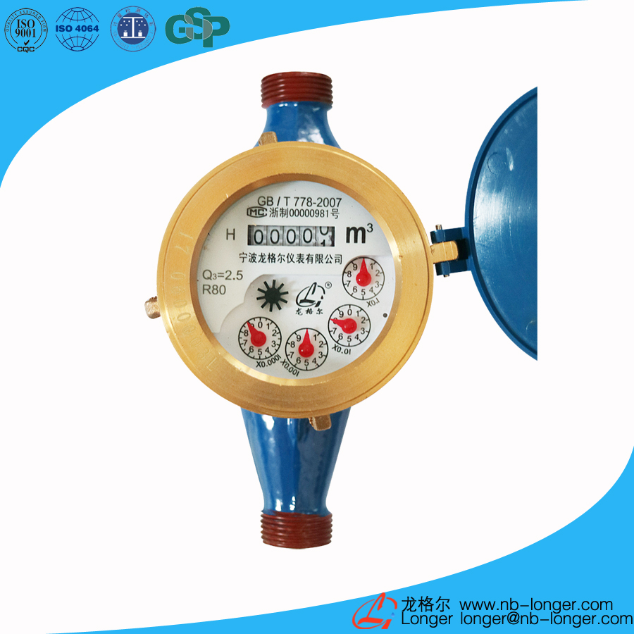
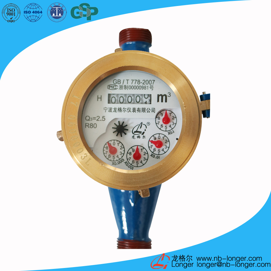
1.Product introduction
Usage: Record the amount of cold water flowing through the water pipe.
2.Main features
The counting part of this water meter adopts special liquid sealing to ensure the surface of the mechanism is anti-freezing. This module has compact structure. The advantage of this module is including high measuring accuracy, small start-up flow rate, antifouling, easy reading, high reliability, nice appearance and etc. It is particularly suitable for water supply network in China. The technical indicators are in line with national GB/T 778.1~3-2007 level of measurement standards (equivalent to the international standard ISO 4064-1~3: 2005.IDT level) requirements.
3.Service conditions
a)Temperature rating:T30(The cold water)T90(The hot water)
b)Pressure rating:Map10
c)Pressure loss rating:△P63
d)Upstream flow field sensitivity rating:U10
e)Downstream flow field sensitivity rating:D5
f)Non-measurable negative test
4.Indication error
a)Low area(Q1≤Q≤Q2)The maximum allowable error is ±5%
b)High area(Q2≤Q≤Q4)The maximum allowable error is ±2%
5.The main technical parameters
Nominal diameter DN (mm) | Overload flow Q4 (m3/h) | Common flow Q3 (m3/h) | Boundary flow Q2 (m3/h) | Minimum flow rate Q1 (m3/h) | Range ratio R(Q3/Q1) | Accuracy grade | Minimum reading (m3) | Maximum reading(m3) |
| DN15 | 3.125 | 2.5 | 0.05 | 0.03125 | 80 | level 2 | 0.0001 | 99999.9999 |
| 0.040 | 0.025 | 100 | ||||||
| 0.032 | 0.020 | 125 | ||||||
| 0.025 | 0.01562 | 160 | ||||||
| DN20 | 5 | 4 | 0.08 | 0.05 | 80 | |||
| 0.064 | 0.040 | 100 | ||||||
| 0.0512 | 0.032 | 125 | ||||||
| 0.040 | 0.025 | 160 | ||||||
| DN25 | 7.875 | 6.3 | 0.126 | 0.07875 | 80 | |||
| 0.1008 | 0.063 | 100 | ||||||
| 0.08064 | 0.0504 | 125 | ||||||
| 0.063 | 0.039375 | 160 | ||||||
| DN40 | 20 | 16 | 0.320 | 0.200 | 80 | 0.001 | 99999.9999 | |
| 0.256 | 0.160 | 100 | ||||||
| 0.2048 | 0.128 | 125 | ||||||
| DN50 | 31.25 | 25 | 0.500 | 0.3125 | 80 | |||
| 0.400 | 0.250 | 100 | ||||||
| 0.320 | 0.200 | 125 |
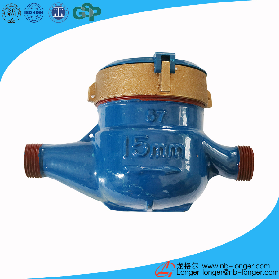
6.Overall size and weight
| Nominal diameter | Length(L) | Width(W) | Height(H) | Weight | Thread connection | |
| mm | Kg | D | ||||
| DN15 | 165 | 94 | 104 | 1.5 | G3/4B | |
| DN20 | 195 | 94 | 106 | 1.7 | G1B | |
| DN25 | 225 | 98 | 124 | 2.4 | G1 1/4B | |
| DN40 | 245 | 124 | 154 | 5 | G 2B | |
| DN50 | 280 | 165 | 179 | 9.5 | Flange connection according to GB4216.4-2008 D=165 D1=125 | |
Note:size and weight are for reference only.

7.Flow error curve

8.Pressure loss curve

Ningbo Longer Meter Co., Ltd.
Address:Hengjie Town, Haishu District, Ningbo
Tel:0574-88281788
Mobile:86-18957821788, 13780002688
E-mail:longer@nb-longer.com

WeChat sweep