

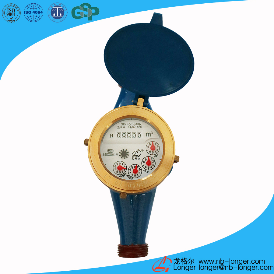
1.Product introduction
Usage: Measure the amount of cold water (hot water) flowing through the water pipe.
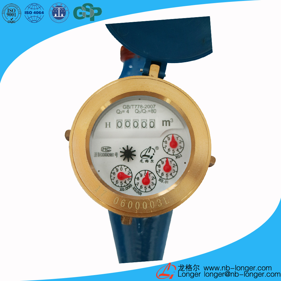
2.Main features
The distinguish characteristics of Multi-Jet Wet Type Vane Wheel Water Meter are high measuring accuracy, and small start-up flow rate. It can keep the counting mechanism full (filled with water). The model has a lot of advantages, including antifouling, easy reading, nice appearance, safety, sanitation, long service life, and etc. The technical indicators are in line with national GB/T 778.1~3-2007 level of measurement standards (equivalent to the international standard ISO 4064-1~3: 2005.IDT level) requirements.
3.Service conditions
a)Temperature rating:T30(The cold water)T90(The hot water)
b)Pressure rating:Map10
c)Pressure loss rating:△P63
d)Upstream flow field sensitivity rating:U10
e)Downstream flow field sensitivity rating:D5
f)Non-measurable negative test
4.The indication error
a)Low area(Q1≤Q≤Q2)The maximum allowable error is ±5%
b)High area(Q2≤Q≤Q4)The maximum allowable error is ±2%
5.The main technical parameters
Nominal diameter DN (mm) | Overload flow Q4 (m3/h) | Common flow Q3 (m3/h) | Boundary flow Q2 (m3/h) | Minimum flow rate Q1 (m3/h) | Range ratio R(Q3/Q1) | Accuracy grade | Minimum reading(m3) | Maximum reading(m3) |
| DN15 | 3.125 | 2.5 | 0.05 | 0.03125 | 80 | level 2 | 0.0001 | 99999.9999 |
| 0.040 | 0.025 | 100 | ||||||
| 0.032 | 0.020 | 125 | ||||||
| 0.025 | 0.01562 | 160 | ||||||
| DN20 | 5 | 4 | 0.08 | 0.05 | 80 | |||
| 0.064 | 0.040 | 100 | ||||||
| 0.0512 | 0.032 | 125 | ||||||
| 0.040 | 0.025 | 160 | ||||||
| DN25 | 7.875 | 6.3 | 0.126 | 0.07875 | 80 | |||
| 0.1008 | 0.063 | 100 | ||||||
| 0.08064 | 0.0504 | 125 | ||||||
| 0.063 | 0.039375 | 160 | ||||||
| DN40 | 20 | 16 | 0.320 | 0.200 | 80 | | 99999.9999 | |
| 0.256 | 0.160 | 100 | ||||||
| 0.2048 | 0.128 | 125 | ||||||
| DN50 | 31.25 | 25 | 0.500 | 0.3125 | 80 | |||
| 0.400 | 0.250 | 100 | ||||||
| 0.320 | 0.200 | 125 |
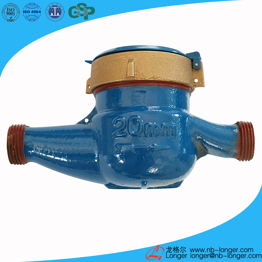
6.Overall size and weight
| Nominal diameter | Length(L) | Width(W) | Height(H) | Weight | Threaded connection | |
| mm | Kg | D | ||||
| DN15 | 165 | 94 | 104 | 1.5 | G3/4B | |
| DN20 | 195 | 94 | 106 | 1.7 | G1B | |
| DN25 | 225 | 98 | 124 | 2.4 | G1 1/4B | |
| DN40 | 245 | 124 | 154 | 5 | G 2B | |
DN50 | 280 | 165 | 179 | 9.5 | Flange connection according to GB4216.4-2008 D=165 D1=125 | |
Note:size and weight are for reference only.

7.Flow error curve

8.Pressure loss curve

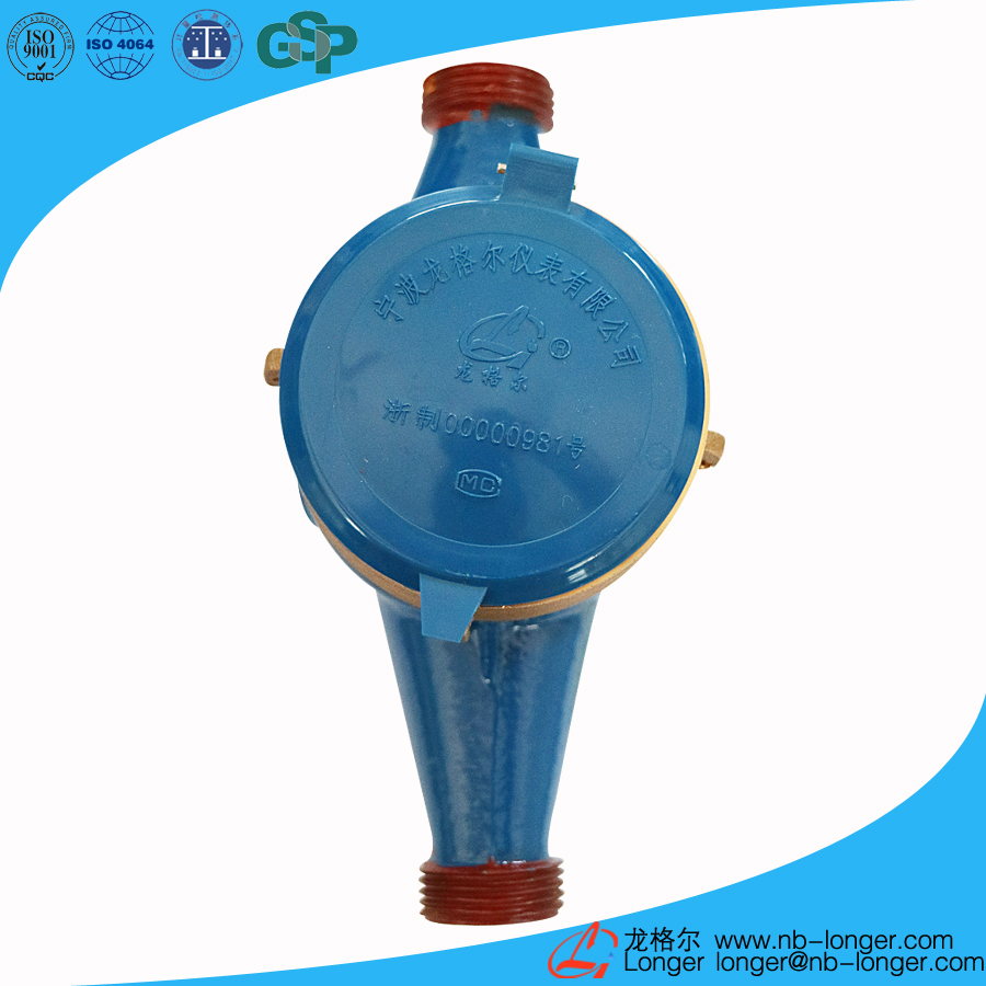
Ningbo Longer Meter Co., Ltd.
Address:Hengjie Town, Haishu District, Ningbo
Tel:0574-88281788
Mobile:86-18957821788, 13780002688
E-mail:longer@nb-longer.com

WeChat sweep